Upload file berupa gambar, dokumen, suara maupun video dapat menggunakan PHP.
Berikut ini adalah cara yang dapat kita lakukan :
1. Langkah 1
Upload file berupa gambar, dokumen, suara maupun video dapat menggunakan PHP.
Berikut ini adalah cara yang dapat kita lakukan :
1. Langkah 1
In this tutorial you will learn how to build a basic rigging system for a low poly character using Blender. Though blender has a Auto-Rigging system called Rigify for bipeds, one must first know how to set up an armature from scratch with Inverse Kinematics controls. You will also learn how to skin the armature to a model and paint weights.
For the purpose of this tutorial I have used a base model which can be purchased on 3docean.
Open a new file and import the base model (File > Import.) You can use any other biped model as well. Right click and select the model, press Alt+G to clear its location, so that it is placed at the center. With the model selected, press Shift+S and then select “Cursor to Selected” to bring the 3D cursor to the origin of the model. Whenever we add a new object, it appears wherever the cursor is. Don’t worry if your model’s center point is at the bottom near the feet unlike in this tutorial.

Press Shift+A and add an Armature Object. Press Z and you can view the object inside.


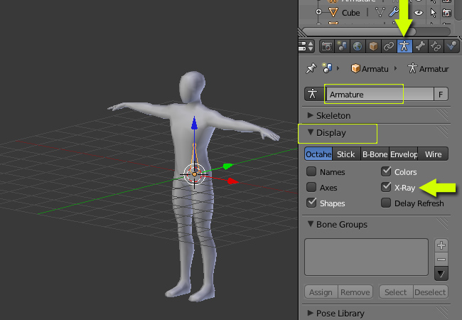
To make the armature visible in shaded view mode, click on the Armatures Tab, in the Display Panel turn on X ray. This will enable us to see armatures through the model. You can also rename your new armature object.
Press 3 on the Numpad to get into the sideview. With the Armature object selected, press TAB to enter into Edit mode. Just as an object’s geometry is edited with the TAB key, armature object’s bones can also be edited with the TAB key (edit mode.) In edit mode, select the bone by Right clicking and move it a ways back as shown below.

Rotate it 90 degrees so that the tip of the bone is inside the body. Place the bone just around the waist line. Remember that we are in edit mode to do all the editing.

Now before going further we must understand the direction of rotation for the bones in human body. All the bones from the lower back to head have the rotation center (pivot point) at their base (bottom.) Also the top bone is the child of the lower bone e.g. the head is the child of neck, which is further a child of the chest and so on.
This means if we rotate or move the lower bone, its child will also be affected. However if we move or rotate a child bone, the parent bone is not affected. The direction of flow is downwards from the pelvis to the feet. So the bone we just created is the parent most bone from which bones for both direction will be extruded. The image below is just for understanding, you don’t have to recreate this.

Now we’ll get back to our armature. In Edit mode, select the tip of the bone with Right-click. Press E to extrude
a bone.

Extrude again a few times for chest, neck and finally for the head.

We have the bones on a little bit of angle in the side view, but in the front view we can see that they are in a straight line.

Select the tip of the first bone again and extrude a bone downwards.

Now we must rename all the bones. Select a bone (in the edit mode) and click on the Bone properties and then rename it. Do it for all bones – pelvis, stomach, chest, neck and head. For the first bone I have named it Base.

Optional: To see the names in the 3D view, open the armature properties and under the display panel click on Names.

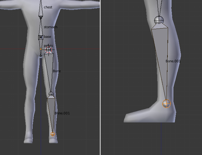
In the front view click on the origin of leg to place the 3D cursor. Now press Shift A and automatically a new bone is added. We are still in the edit mode. Save your file.

Select the tip of the new bone and press G to grab it down to the knee.

Press E again to extrude another bone to the ankle. Make sure the two leg bones are not in a straight line, rather they should be little bit angled or bent.
Extrude a bone for the foot and another for the toe.

Now right click on the thigh bone to select it. In the Bone properties toolbar, rename the bone to thigh.l with a .L extension. This way blender will recognize the bone as left or right, making it easy for posing and editing in mirror symmetry later.

Similarly name the rest of the bones with anything you like but with a .L extension – lowerleg.l, foot.l and finally toe.l.

Select the thigh.l bone and in the Bone properties toolbar, under the Relations panel, set Parent to the pelvis bone. Now the thigh bone is a child of the pelvis bone. Make sure the Connected check box is unchecked, as we don’t want these bones to be connected together, just follow the parent-child relationship. Alternatively you can parent it with the Ctrl+P command. Select the thigh bone first and then the pelvis and press Ctrl+P to make it a parent. Select keep offset when asked.

Press 1 on the numpad to get into the Front view. Left-click on the left side of the chest, just below the neck, on a point where you want to start the collar bone.

Press Shift+A to create a bone.

Select the tip of the new bone and press G to move it right on the shoulder.

Now extrude out a bone to the elbow, and then again until the palm.


Check the alignment in the top view as well.

In the Bone properties, rename all the new bones with anything you want, but with a .L extension. I have named them – collar.l, upperarm.l and lowerarm.l

Select the collar.L bone and in the Bone properties set the Chest bone as its parent. This way it will follow the chest bone.

Now extrude out the palm from the lower arm bone.

Press E again to extrude out the finger bones three times.

Now select all the Finger bones while holding Shift and then right clicking them individually, or by using the B key and drag selecting all of them. Press Shift+D to duplicate the set and move the mouse to place them on another finger. Adjust the tips to match the finger joints. Duplicate the set again for the rest of the fingers.

You will notice that the new duplicated sets are already a child of the palm bone, as the first finger set was the child from which we duplicated the new ones.
Check from the side view also.

Rename all the new bones with a .L extension. (Palm.l, f1.l etc…)

Similarly duplicate a finger bone set for the thumb. Place and adjust the bones to match the thumb joints. Press Z to see the joint loops. Rename them again with a .L extension (ta.l, tb.l, tc.l)

Now we have finished setting up all the basic deforming bones for left side. We will duplicate and mirror these for the right side. Press TAB to exit edit mode. With the Armature object selected, press Shift+S and select ‘Cursor to Selected’. This will bring the 3D cursor to the origin point of the object that is the center of the armature.

With the Armature object selected, press TAB again to enter into Edit mode. Select all the left bones (press B to drag select or hold Shift and then Right click for multiple select.) Make sure you don’t select any center bones or leave out any of the .L bones.

Press Shift+D to make a duplicate, Right-click anywhere to confirm the default position of the new bones. The new bones will be sharing the same position with the old bones. Also the new bones will be the selected ones now.

In the Header of 3D view (at the bottom), change the Pivot point to 3D cursor. This will make the 3D cursor the center of deformations like Rotation and Scaling, etc… You can also do this with the keyboard by pressing the . (period) key.

Click on the Armature Menu, go to Mirror and then finally click on X Local. The duplicated bones will be mirrored with the 3D cursor being the center point of rotation.

You will notice that the new bones have a .l.001, .l.002…extension. Press W and click on Flip Names. This will replace the .l.001 to .r (right). To toggle view names on or off, check or uncheck ‘Names’ in the Armature properties panel.

We now have all the deforming bones setup complete.

Press CTRL+TAB to enter into Pose mode (or select Pose mode from the header bar.) Right-click on any bone and press R to rotate any bone and see some action. You will see that by rotating a parent bone, all the child bones get affected. Similarly rotating or moving the first bone (base) we created, will effect the complete structure. Select all the bones with the A key in the Pose mode, and press Alt+G to reset the bone’s position to default. Press Alt+R to reset the bone’s rotation to default.

Next we will add an IK setup for the legs. This will help with posing and animation. With the Armature selected (or in Pose mode,) press TAB to get into Edit mode. In the 3D view, press T to toggle on the Tool shelf, and turn on the X-Axis Mirror under the Armature Options. This will mirror any editing done on either side.

In the side view, select the tip of the leg bone and press E, and Extrude out a single bone.

Name the new bones. I have named them ik-leg.l and ik-leg.r. In the Bone Properties window, under the Relations Panel. Delete the name of the parent bone, as we don’t want it to be a child on any. Uncheck the Connected checkbox. This way we can easily move the ik bone around.

Now we have to create a pole target of the IK bones. You will understand the need for this later. For this you can create two new bones and place them in front of the knee, OR you can duplicate any existing bone and make it child of the new ik-leg bone, so that it will follow this bone.
For now, let us duplicate the foot bone. Select the foot bone by Right-clicking and then press Shift+D to make a Duplicate. As the X-axis Mirror is on, the other side will automatically be created and edited. Move the bone in front of the knee. You might need to switch back to ‘median point’ as the pivot point for rotation by pressing , (comma). Name them knee.l and knee.r , make them a child of the ik-leg bones respectively. i.e. knee.l a child of ik-leg.l, and knee.r a child of ik-leg.r


Press Ctrl+TAB to enter into Pose Mode. Right-click on the lower-leg.l bone to select it.

In the Bone Constraint Properties, add a new constraint – Inverse Kinematics, to the lower leg bone.

For the IK target, we use the ik-leg.l bone of the object Armature. So first select the Armature object from the drop down list (or you can type the name.) Then select the Bone (ik-leg.l) in the bone field and set the chain length to 2, so that it effects the last two bones of the chain – lowerleg and thigh bone.

You will notice some weird rotation of the leg. You can slide and adjust the Pole Angle to turn it back to normal.

A value of 90 degrees was perfect for me this time.

Now select the lower-leg.r (right) bone and add the Inverse Kinematics Constraint to it. Use Ik-leg.r as the target bone (of the Armature object) and knee.r as the Pole target. Set the chain length to 2 and Pole angle to around 90 degrees.

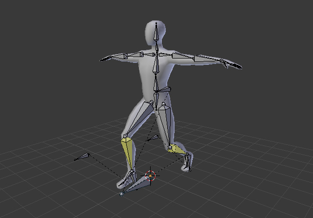
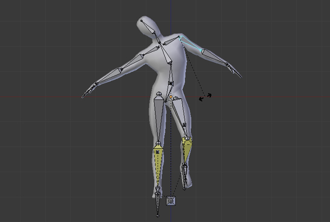
Press Ctrl+TAB to get into Pose mode and play with the new IK bone. Select the ik controller and press G to move it around. Select the base bone and move it around. To reset the position and rotation, select all bones with by pressing the A key, and press Alt+G (to reset the location) and Alt+R (to reset the rotation.)

Enter into Edit mode by hitting TAB and place the 3D cursor on the center. Press 3 on the numpad to get into the side view. Click at the bottom of the feet to position the 3D cursor there. As it was in the center of the object, it will remain in the center when viewed from the front. if not, place it in center between both feet.

Press Shift+A to add another (Last) bone. Rename this as ‘Root’. This will be the mother of all bones. While animating, we can move this bone to move the whole Armature in Pose mode.

Right-click on the tip of the bone to select it, and press 3 on the numpad to get into the side view. Press G and move the tip forward, holding Ctrl while moving.

Now we will make this root bone a parent of the Base bone and the IK bones. Select the Base bone and in it’s properties, type the name here (‘Root’) in the parent field.

Similarly do the same for the ik controllers.


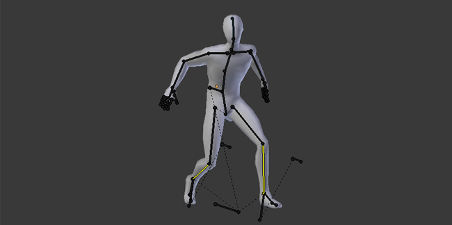
We now have a basic setup. Play with some poses (in Pose mode). To move the legs, use the IK controllers. To adjust the direction of the knees, move the knee bones (Pole targets.)

Press Alt+G to reset the location of the bones, and Alt+R to reset the rotations. The Armature is ready and we can start skinning the model to it.

Select the Armature by Right-clicking, and enter into Edit mode with the TAB key. Select the Root bone, and in it’s Bone properties, uncheck deform.Do the same for all ‘controller’ bones like IK-lrg.lr, ik-leg.l, knee.l, knee.r and the base bone.
These bones help in controlling the armature and not in deforming the mesh, so we don’t want even a single vertex of the model to get assigned to these bones. The remaining bones will be the ones which will deform the mesh.


Press TAB to exit Edit mode. If you are in Pose mode, then press Ctrl+TAB to switch to Object mode (or select the mode in the header.)

Now Right-click on the model to select it first, and then hold the Shift key and Right-click on the armature object. Press Ctrl+P to make it (Armature – the object which is selected last) a parent. Choose the ‘With Automatic Weights’ option. This way Blender will automatically assign vertices of the model to the respective bones according to the bone weight and placement.

Right-click only on the Armature to selected it, press Ctrl+Tab to enter into Pose mode. Play around by Rotating the bones, you’ll see that the mesh now deforms along the bones.
In the Modifiers Panel, you’ll see that an Armature modifier is automatically added to the model. Right-click on the model to select it and see its properties.

Also new vertex groups are made with the name of each bone. These groups are assigned to the respective bones automatically. We don’t have to do anything yet.

While in Pose mode, we see that the mesh isn’t deforming in same places to way we want. For this we can alter the effect of the bones on the vertices, using a method called Weight Painting.

In the Armature Properties click on the Stick button, under the Display Panel. This will display the bones as Sticks.

Select the mesh by Right-clicking, and in the Object Properties (under the Display Panel) turn on Wire. This will be helpful while weight painting.

With the Armature in POSE MODE and a bone is selected. Right-click on the mesh object to select it. Press Ctrl+TAB to get into Weight Painting mode, or you can select the mode in the header section of the 3D view (at the bottom of 3D view)

Press T to toggle on the Tool Shelf. While in Weight Paint Mode, you’ll see all the tools related to this mode.

You can increase the weight of the vertices you would like to be effected by a particular bone. Here for example I have increased the side vertices with 0.5 weight to create a nice deformation. You can still check by rotating and moving the bones while in weight painting. Right click on any bone to see its weight on the mesh.

Similarly if don’t want some vertices to be effected by a bone, just paint it with a lower weight value.

Do check the BACK SIDE too wherever you do the painting.

Experiment with Weight Painting. Rotate the bones to see the effect.

For the joints, the middle loop can be shared with both bones to create a round shape. You can use this on most joints wherever you need roundness.


Do check the BACK SIDE too where ever you do the painting.
You can also edit the geometry by pressing TAB to get into Edit mode. Here I have pulled out some vertices to get a more pointy elbow.


Do check the BACK SIDE too where ever you do the painting.
Similarly check for all bones. Paint with a 0.0 (or close to zero) weight brush if you don’t want the vertices to get effected, and paint with higher values if you want the vertices to deform. You can also share one vertex with two bones with different weight to have a nice deformation. A good deforming rig depends upon how good the weight painting is.


We now have our character ready for posing or animation.
There are different approaches for creating the pelvis setup. Feel free to explore, experiment and learn.